Referred links:
https://www.cisco.com/c/en/us/support/docs/lan-switching/integrated-routing-bridging-irb/200650-Understanding-Bridge-Virtual-Interface.html
https://community.cisco.com/t5/switching/bvi-what-is-it-and-what-are-its-uses/td-p/2373489
https://www.cisco.com/c/en/us/support/docs/lan-switching/integrated-routing-bridging-irb/17054-741-10.html
https://www.juniper.net/documentation/en_US/junos/topics/concept/interfaces-understanding-transient-interfaces.html
http://www.semsim.com/ccna/course/demo/dswmedia/20303/2030301_01.htm
---------------------------------------------------------------------------------------------------------------------
I have been working on routers for the last 7 years. Have come across various types of interfaces in routers, some of which i find worth discussing.
Routers typically contain several different types of interfaces suited to various functions. For the interfaces on a router to function, you must configure them.
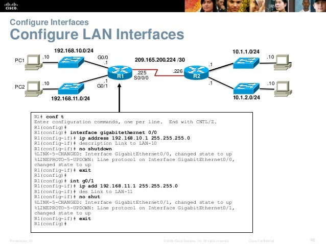
In Figure I, PCs A and B are connected to VLANs that are in turn separated by a router. This illustrates the common misconception that a single VLAN can have a router-based connection in the middle.
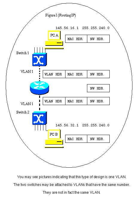
This figure also shows the flow of the three layers of headers for a frame traversing the links from PC A to PC B.
As the frame flows through the switch, the VLAN header is applied because the connection is a trunk link. There may be several VLANs communicating across the trunk.
The router terminates the VLAN layer and the MAC layer. It examines the destination IP address and forwards the frame appropriately. In this case, the IP frame is to be forwarded out of the port toward PC B. This is also a VLAN trunk and so a VLAN header is applied.
Although the VLAN connecting Switch 2 to the router can be called the same number as the VLAN connecting Switch 1 to the router, it is actually not the same VLAN. The original VLAN header is removed when the frame arrives at the router. A new header may be applied as the frame exits the router. This new header may include the same VLAN number that was used in the VLAN header that was stripped when the frame arrived. This is demonstrated by the fact that the IP frame moved through the router without a VLAN header attached, and was forwarded based on the contents of the IP destination address field, and not on a VLAN ID field.
Because the two VLAN trunks sit on opposite sides of the router, they must be different IP subnets.
Useful when you want to bridge two interfaces on the router and want them to be in the same Layer-2 broadcast domain.Let us consider a scenario where you want to connect two PCs to the router and have them part of the same subnet in addition to internet access from both the PCs.
When configuring software bridging, you define a group of interfaces that are bridged - the router performs bridging (i.e. software-based switching) of frames between all member ports of a bridge group, in essence forming a single broadcast domain - an IP subnet. If the devices in the common bridge group want to access other IP networks, they need a gateway, so you create an associated interface BVI that is also a part of the bridge group, and devices in the bridge group then use the IP address of the BVI interface as their gateway.
For example, imagine a router with two Fast Ethernet interfaces:
You rarely configure bridging exactly this way these days, as switches are orders of magnitude faster and have way more ports. Still, there are situations where you need to bridge two interfaces, taking packets out of frames of one technology and putting them into frames of a different technology, without routing them, just repackaging but still carrying them between interfaces. This is often done in, say, DSL if the router is configured to act in bridge mode - take IP packets coming to Ethernet interface and simply repackage them into PPP or ATM+AAL5 cells on the DSL WAN port (and vice versa).
https://www.cisco.com/c/en/us/support/docs/lan-switching/integrated-routing-bridging-irb/200650-Understanding-Bridge-Virtual-Interface.html
https://community.cisco.com/t5/switching/bvi-what-is-it-and-what-are-its-uses/td-p/2373489
https://www.cisco.com/c/en/us/support/docs/lan-switching/integrated-routing-bridging-irb/17054-741-10.html
https://www.juniper.net/documentation/en_US/junos/topics/concept/interfaces-understanding-transient-interfaces.html
http://www.semsim.com/ccna/course/demo/dswmedia/20303/2030301_01.htm
---------------------------------------------------------------------------------------------------------------------
I have been working on routers for the last 7 years. Have come across various types of interfaces in routers, some of which i find worth discussing.
Routers typically contain several different types of interfaces suited to various functions. For the interfaces on a router to function, you must configure them.
The interfaces on a router provide network connectivity to the router.
The console and auxiliary ports are used for managing the router.
Routers also have ports for LAN and WAN connectivity.
LAN/Port Interface:
The LAN interfaces usually include Ethernet, Fast Ethernet, Fiber Distributed Data Interface (FDDI), or Token Ring.
VLAN Interface:
If the ports on a switch belong to the same VLAN and the switch is capable of multilayer switching, you can create an interface Vlan for that VLAN and allow the hosts in that VLAN to use the IP address of the interface Vlan as their default gateway.In Figure I, PCs A and B are connected to VLANs that are in turn separated by a router. This illustrates the common misconception that a single VLAN can have a router-based connection in the middle.
This figure also shows the flow of the three layers of headers for a frame traversing the links from PC A to PC B.
As the frame flows through the switch, the VLAN header is applied because the connection is a trunk link. There may be several VLANs communicating across the trunk.
The router terminates the VLAN layer and the MAC layer. It examines the destination IP address and forwards the frame appropriately. In this case, the IP frame is to be forwarded out of the port toward PC B. This is also a VLAN trunk and so a VLAN header is applied.
Although the VLAN connecting Switch 2 to the router can be called the same number as the VLAN connecting Switch 1 to the router, it is actually not the same VLAN. The original VLAN header is removed when the frame arrives at the router. A new header may be applied as the frame exits the router. This new header may include the same VLAN number that was used in the VLAN header that was stripped when the frame arrived. This is demonstrated by the fact that the IP frame moved through the router without a VLAN header attached, and was forwarded based on the contents of the IP destination address field, and not on a VLAN ID field.
Because the two VLAN trunks sit on opposite sides of the router, they must be different IP subnets.
BVI (Bridged Virtual Interface):
Useful when you want to bridge two interfaces on the router and want them to be in the same Layer-2 broadcast domain.Let us consider a scenario where you want to connect two PCs to the router and have them part of the same subnet in addition to internet access from both the PCs.
When configuring software bridging, you define a group of interfaces that are bridged - the router performs bridging (i.e. software-based switching) of frames between all member ports of a bridge group, in essence forming a single broadcast domain - an IP subnet. If the devices in the common bridge group want to access other IP networks, they need a gateway, so you create an associated interface BVI that is also a part of the bridge group, and devices in the bridge group then use the IP address of the BVI interface as their gateway.
For example, imagine a router with two Fast Ethernet interfaces:
bridge irb

!

interface FastEthernet0/0

 no ip address

 no shutdown

 bridge-group 1

!

interface FastEthernet0/1

 no ip address

 no shutdown

 bridge-group 1

!

interface BVI1

 ip address 10.0.0.1 255.255.255.0

 no shutdown

!

bridge 1 route ip
This configuration would make your router to basically behave as a 2-port "switch" on its Fa0/0 and Fa0/1 interfaces, and devices connected to these ports would use the 10.0.0.1 as their default gateway to other networks.
You rarely configure bridging exactly this way these days, as switches are orders of magnitude faster and have way more ports. Still, there are situations where you need to bridge two interfaces, taking packets out of frames of one technology and putting them into frames of a different technology, without routing them, just repackaging but still carrying them between interfaces. This is often done in, say, DSL if the router is configured to act in bridge mode - take IP packets coming to Ethernet interface and simply repackage them into PPP or ATM+AAL5 cells on the DSL WAN port (and vice versa).
IRB Sample Configuration
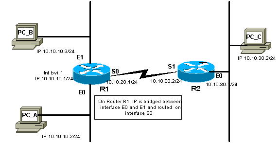
This configuration is an example of IRB. The configuration allows bridging IP between two Ethernet interfaces, and routing IP from bridged interfaces using a Bridged Virtual Interface (BVI). In the following network diagram, when PC_A attempts to contact PC_B, the router R1 detects that the destination's (PC_B) IP address is in the same subnet, so the packets are bridged by router R1 between interface E0 and E1. When PC_A or PC_B attempt to contact PC_C, the router R1 detects that the destination's (PC_C) IP address is in a different subnet, and the packet is routed using the BVI. This way, IP protocol is bridged as well as routed on the same router.Network Diagram

No comments:
Post a Comment