Wednesday, January 22, 2020

BGP v/s OSPF

References:
https://serverfault.com/questions/185635/what-is-the-difference-between-bgp-and-ospf

https://community.fs.com/blog/ospf-vs-bgp-routing-protocol-choice.html

https://techdifferences.com/difference-between-ospf-and-bgp.html
-----------------------------------------------------------------------------------------------------------------------

It will be worthwhile comparing two popular routing protocols widely used for making routing decisions across the internet.

BGP stands for Border Gateway Protocol
OSPF stands for Open shttps://techdifferences.com/difference-between-ospf-and-bgp.htmlhortest distance First.

what is ospf vs bgp


 BGP is exterior, OSPF is interior

OSPF is an intranetwork protocol which is used with in an AS(Autonomous System) while BGP is an inter network protocol and hence used between two different AS

If you are doing internal routing, i.e. routing within a site, company, or campus, you will want to use OSPF. Typically BGP is needed at a site edge, where you route out to the public internet. In small and medium size networks, static routes to the outside will usually be preferable to setting up BGP. If you have a complicated multi-homed site, regardless of size, you might consider BGP. 

OSPF vs BGP

Here is a chart summarizing the differences of OSPF vs BGP:

OSPF BGP
Gateway Protocol Internal gateway protocol External gateway protocol   
Implementation Easy Complex
Convergence Fast Slow
Design Hierarchical network possible Meshed
Need for device resources Memory and CPU Intensive Scaling is better in BGP although it relies on the size of the routing table
Size of the networks Used on primarily smaller scale network which could be administered centrally Mostly used on large scale networks such as the internet
Function The fastest route is preferred over shortest Best path is determined for the datagram
Algorithm Used Dijkstra algorithm Best path algorithm
Protocol IP TCP     

 Implementation    Easy                                      Tough
 Works on Protocol 89                                          179

Although BGP is used between multiple autonomous systems as an external routing protocol, many network giants like Microsoft and Facebook would use it internally – in this case, BGP is typically fit for very large networks which OSPF fails to handle. One of the many reasons that BGP does not function well as an internal gateway protocol is that it is very slow to converge.

Tuesday, January 21, 2020

Networking commands on Linux

* Many sites referred for information on this page

1. route -n

The route -n command lists the routing table; the -n option displays the results as IP addresses only and does not attempt to perform a DNS lookup which would replace the IP address with host names if they are available.


[root@host1 ~]# route -n Kernel IP routing table Destination     Gateway         Genmask         Flags Metric Ref    Use Iface 0.0.0.0         192.168.0.254   0.0.0.0         UG    100    0        0 eno1 192.168.0.0     0.0.0.0         255.255.255.0   U     100    0        0 eno1
Figure 1: A simple routing table.
The default gateway is always shown with the destination 0.0.0.0 when the -n option is used. If -n is not used, the word "Default" appears in the Destination column of the output. The IP address in the Gateway column is that of the outbound gateway router. The netmask of 0.0.0.0 for the default gateway means that any packet not addressed to the local network or another outbound router by additional entries in the routing table are to be sent to the default gateway regardless of the network class.

The Iface (Interface) column in Figure 1 is the name of the outbound NIC, in this case, eno1. For hosts that are acting as routers, there will likely be at least two and sometimes more NICs used. Each NIC used as a route will be connected to a different physical and logical network. The flags in the Flag column indicate that the route is Up (U) and which is the default Gateway (G). Other flags may also be present.

The netstat -rn command produces very similar results.


1.5 netstat
 
The netstat command, meaning network statistics, is a Command Prompt command used to display very detailed information about how your computer is communicating with other computers or network devices.


2. arp –a : Prints the arp table
arp –s [pub] to add an entry in the table
arp –a –d to delete all the entries in the ARP table

arp -n

command to view all of the MAC addresses that your host has stored in its arp table.


3.  The ifconfig command is used to get the information of active network-interfaces in a Unix-like operating system such as Linux, whereas ipconfig is used in the Windows OS.

4. Ping is a networking utility program or a tool to test if a particular host is reachable. It is a diagnostic that checks if your computer is connected to a server. Ping, a term taken from the echo location of a submarine, sends data packet to a server and if it receives a data packet back, then you have a connection.

—- sends an ICMP echo message (one packet) to a host. This may go continually until you hit Control-C. Ping means a packet was sent from your machine via ICMP, and echoed at the IP level. ping tells you if the other Host is Up.


5.
telnet host —- talk to “hosts” at the given port number. By default, the telnet port is port 23. Few other famous ports are:
7 – echo port,
25 – SMTP, use to send mail
79 – Finger, provides information on other users of the network
Use control-] to get out of telnet.

6. route add|delete [-net|-host] (ex. route add 192.168.20.0/24 192.168.30.4) to add a route
route flush : it removes all the routes

route add —- The route command is used for setting a static (non-dynamic by hand route) route path in the route tables. All the traffic from this PC to that IP/SubNet will go through the given Gateway IP. It can also be used for setting a default route; i.e., send all packets to a particular gateway, by using 0.0.0.0 in the pace of IP/SubNet.

route add -net 0.0.0.0 192.168.10.2 : to add a default route


 7.
traceroute —- Useful for tracing the route of IP packets. The packet causes messages to be sent back from all gateways in between the source and destination by increasing the number of hopes by 1 each time.

8. 
nslookup —- Makes queries to the DNS server to translate IP to a name, or vice versa. eg. nslookup facebook.com will gives you the IP of facebook.com


9.

Important Files:

/etc/hosts —- names to ip addresses
/etc/networks —- network names to ip addresses
/etc/protocols —– protocol names to protocol numbers
/etc/services —- tcp/udp service names to port numbers


Router interfaces

Referred links:

 https://www.cisco.com/c/en/us/support/docs/lan-switching/integrated-routing-bridging-irb/200650-Understanding-Bridge-Virtual-Interface.html

https://community.cisco.com/t5/switching/bvi-what-is-it-and-what-are-its-uses/td-p/2373489

https://www.cisco.com/c/en/us/support/docs/lan-switching/integrated-routing-bridging-irb/17054-741-10.html 

https://www.juniper.net/documentation/en_US/junos/topics/concept/interfaces-understanding-transient-interfaces.html 

http://www.semsim.com/ccna/course/demo/dswmedia/20303/2030301_01.htm
---------------------------------------------------------------------------------------------------------------------

I have been working on routers for the last 7 years. Have come across various types of interfaces in routers, some of which i find worth discussing.

Routers typically contain several different types of interfaces suited to various functions. For the interfaces on a router to function, you must configure them.

The interfaces on a router provide network connectivity to the router. The console and auxiliary ports are used for managing the router. Routers also have ports for LAN and WAN connectivity.

LAN/Port Interface:

The LAN interfaces usually include Ethernet, Fast Ethernet, Fiber Distributed Data Interface (FDDI), or Token Ring.
Presentation_ID 46© 2008 Cisco Systems, Inc. All rights reserved. Cisco Confidential
Configure Interfaces
Configure LAN In...

VLAN Interface:

If the ports on a switch belong to the same VLAN and the switch is capable of multilayer switching, you can create an interface Vlan for that VLAN and allow the hosts in that VLAN to use the IP address of the interface Vlan as their default gateway.

In Figure I, PCs A and B are connected to VLANs that are in turn separated by a router. This illustrates the common misconception that a single VLAN can have a router-based connection in the middle.
router_vlan1.gif
This figure also shows the flow of the three layers of headers for a frame traversing the links from PC A to PC B.

As the frame flows through the switch, the VLAN header is applied because the connection is a trunk link. There may be several VLANs communicating across the trunk.
The router terminates the VLAN layer and the MAC layer. It examines the destination IP address and forwards the frame appropriately. In this case, the IP frame is to be forwarded out of the port toward PC B. This is also a VLAN trunk and so a VLAN header is applied.

Although the VLAN connecting Switch 2 to the router can be called the same number as the VLAN connecting Switch 1 to the router, it is actually not the same VLAN. The original VLAN header is removed when the frame arrives at the router. A new header may be applied as the frame exits the router. This new header may include the same VLAN number that was used in the VLAN header that was stripped when the frame arrived. This is demonstrated by the fact that the IP frame moved through the router without a VLAN header attached, and was forwarded based on the contents of the IP destination address field, and not on a VLAN ID field.

Because the two VLAN trunks sit on opposite sides of the router, they must be different IP subnets.


BVI (Bridged Virtual Interface):


Useful when you want to bridge two interfaces on the router and want them to be in the same Layer-2 broadcast domain.Let us consider a scenario where you want to connect two PCs to the router and have them part of the same subnet in addition to internet access from both the PCs.

When configuring software bridging, you define a group of interfaces that are bridged - the router performs bridging (i.e. software-based switching) of frames between all member ports of a bridge group, in essence forming a single broadcast domain - an IP subnet. If the devices in the common bridge group want to access other IP networks, they need a gateway, so you create an associated interface BVI that is also a part of the bridge group, and devices in the bridge group then use the IP address of the BVI interface as their gateway.

For example, imagine a router with two Fast Ethernet interfaces:
bridge irb

!

interface FastEthernet0/0

 no ip address

 no shutdown

 bridge-group 1

!

interface FastEthernet0/1

 no ip address

 no shutdown

 bridge-group 1

!

interface BVI1

 ip address 10.0.0.1 255.255.255.0

 no shutdown

!

bridge 1 route ip
This configuration would make your router to basically behave as a 2-port "switch" on its Fa0/0 and Fa0/1 interfaces, and devices connected to these ports would use the 10.0.0.1 as their default gateway to other networks.
You rarely configure bridging exactly this way these days, as switches are orders of magnitude faster and have way more ports. Still, there are situations where you need to bridge two interfaces, taking packets out of frames of one technology and putting them into frames of a different technology, without routing them, just repackaging but still carrying them between interfaces. This is often done in, say, DSL if the router is configured to act in bridge mode - take IP packets coming to Ethernet interface and simply repackage them into PPP or ATM+AAL5 cells on the DSL WAN port (and vice versa).

IRB Sample Configuration

This configuration is an example of IRB. The configuration allows bridging IP between two Ethernet interfaces, and routing IP from bridged interfaces using a Bridged Virtual Interface (BVI). In the following network diagram, when PC_A attempts to contact PC_B, the router R1 detects that the destination's (PC_B) IP address is in the same subnet, so the packets are bridged by router R1 between interface E0 and E1. When PC_A or PC_B attempt to contact PC_C, the router R1 detects that the destination's (PC_C) IP address is in a different subnet, and the packet is routed using the BVI. This way, IP protocol is bridged as well as routed on the same router.

Network Diagram

router_vlan5.gif

IGMP Snooping

References:
https://blogs.vmware.com/vsphere/2013/05/vxlan-series-multicast-basics-part-2.html

https://www.juniper.net/documentation/en_US/junos/topics/concept/igmp-snooping-qfx-series-overview.html

https://mrncciew.com/2012/12/25/igmp-basics/


How does layer 2 network devices know which nodes are interested in which conversations or multicast groups?

The layer 2 switches monitor the IGMP query and report messages to find out which switch ports are subscribed to which multicast group. This functionality of a layer 2 switch is called IGMP snooping.

The diagram below shows an example where there are two servers on the right streaming two different webcasts A and B. The users on the left choose to subscribe to a particular webcast by sending IGMP report messages.

IGMP Join request
The Layer 2 switch monitors IGMP packets sent by the users and makes entry in the forwarding table about the membership to particular multicast addresses. As you can see that multicast group address 239.1.1.100 is associated with Webcast A and 239.1.1.101 with Webcast B. In this example Port 1 and 2 are members of the multicast group 239.1.1.100 while Port 3 and 4 are members of 230.1.1.101.

The diagram below shows how the Webcast A packets with destination IP address 239.1.1.00 (Orange Arrow) sent to port 10 are only replicated to port 1 and 2 of the switch. Similarly the Webcast B traffic (Green Arrow) is only sent to port 3 and 4. User connected to port 5 is not subscribed to any Webcasts so it won’t receive any multicast traffic.

Multicast Packets
This shows how IGMP snooping capability on a physical switch optimizes the multicast packet delivery.

*Note that in this example each user has joined only one multicast group, but in reality they can join any number of multicast groups.

Why do you need IGMP querier ?

IGMP querier is the function of a router and it is important to enable that for a proper IGMP snooping operation on layer 2 switches. We looked at how users join a multicast group by sending IGMP query messages. These messages are sent to the multicast router or IGMP querier.

Without an IGMP querier to respond to, users do not send periodic membership requests. As a result, the entries in the layer 2 switch times out and multicast traffic is not delivered. In any given subnet, one multicast router acts as an IGMP querier.

Image result for IGMP snooping querier


 The IGMP querier sends out the following types of queries to hosts:
  • General query—Asks whether any host is listening to any group.

  • Group-specific query—(IGMPv2 and IGMPv3 only) Asks whether any host is listening to a specific multicast group. This query is sent in response to a host leaving the multicast group and allows the router to quickly determine if any remaining hosts are interested in the group.

  • Group-and-source-specific query—(IGMPv3 only) Asks whether any host is listening to group multicast traffic from a specific multicast source. This query is sent in response to a host indicating that it is not longer interested in receiving group multicast traffic from the multicast source and allows the router to quickly determine any remaining hosts are interested in receiving group multicast traffic from that source.

    Hosts that are multicast listeners send the following kinds of messages:

  • Membership report—Indicates that the host wants to join a particular multicast group.

  • Leave report—(IGMPv2 and IGMPv3 only) Indicates that the host wants to leave a particular multicast group.


    How Hosts Join and Leave Multicast Groups


    IGMP-2

    Hosts can join multicast groups in two ways:
  • By sending an unsolicited IGMP join message to a multicast router that specifies the IP multicast group the host wants to join.
  • By sending an IGMP join message in response to a general query from a multicast router.
    IGMP-3


    A multicast router continues to forward multicast traffic to a VLAN provided that at least one host on that VLAN responds to the periodic general IGMP queries. For a host to remain a member of a multicast group, it must continue to respond to the periodic general IGMP queries. 

     IGMP-4

    Hosts can leave a multicast group in either of two ways:
  • By not responding to periodic queries within a particular interval of time, which is considered a “silent leave.” This is the only leave method for IGMPv1 hosts.
  • By sending a leave report. This method can be used by IGMPv2 and IGMPv3 hosts.

Advantages of IGMP Snooping:

1. 
A multicast MAC address can never be the source address for a packet. As a result, when a device receives traffic for a multicast destination address, it floods the traffic on the relevant VLAN, sending a significant amount of traffic for which there might not necessarily be interested receivers.

IGMP snooping prevents this flooding thus the device conserves bandwidth by sending multicast traffic only to interfaces connected to devices that want to receive the traffic, instead of flooding the traffic to all the downstream interfaces in a VLAN.

2.
Improved security—Prevents denial of service attacks from unknown sources.


Thursday, January 16, 2020

TCAM inside routers

Links referred:
 http://www.enterprisenetworkingplanet.com/netsysm/article.php/3527301/On-Your-Network-What-the-Heck-is-a-TCAM.htm

https://howdoesinternetwork.com/2015/tcam-memory

https://www.metaswitch.com/blog/save-some-cache.-trash-the-tcam

http://slideplayer.com/slide/15897722/


TCAM is a Ternary CAM. This allows the operating system to match a third state, "X." The X state is a "mask," meaning its value can be anything.


This lends itself well to networking, since netmasks (define) operate this way. To calculate a subnet address we mask the bits we don't care about, and then apply the logical AND operation to the rest. Routers can store their entire routing table in these TCAMs, allowing for very quick lookups.

Besides Longest-Prefix Matching, TCAM in today’s Routers and Multilayer Switch devices are used to store ACL, QoS and other things from upper-layer processing. TCAM architecture and the ability of fast lookup enables us to implement Access-Lists without an impact on router/switch performance.

Devices with this ability mostly have more TCAM memory modules in order to implement Access-List in both directions and QoS at the same time at the same port without any performance impact. All those different functions and their lookup process towards a decision is made in parallel.


Pros:

1. Works faster as compared to same logic if written in SW

 2. TCAM main characteristic is that it is able to search all its entries in parallel. It means that no matter how many address prefixes are stored in TCAM, router will find the longest prefix match in one iteration.

3. TCAM's performance is deterministic

4. Updating TCAM based entries is easy


Cons:

1. The additional circuitry, required to perform the comparative detection, means chips having TCAM are not cheap, rather very expensive

2. TCAM memory is very power hungry. It's size and the nature of its parallelism (i.e the fact that each comparative circuit is firing simultaneously on each clock cycle) results in it drawing significantly more power and generating considerably more heat than typical RAM.


Alternatives to TCAM:


1. A software-based session border controller can make use of level 3 cache to perfectly replicate the functionality of a TCAM while making use of HASH/TRIE etc based solutions which are a little tough to implement

Points to remember:

1.  IP prefixes need to be sorted before they are stored in TCAM so that longest prefixes are on upper position with higher priority (lower address location) in a table. This enables us to always select the longest prefix from given results an thus enables Longest-Prefix Matching.


Tuesday, January 14, 2020

Policy Based Routing (PBR)

Referred site(s):

https://www.slideshare.net/khnog/policy-based-routing-pbr

https://www.cioby.ro/2016/09/08/configuring-policy-based-routing-on-cisco-asa/

https://www.internetworks.in/2018/11/policy-based-routing-pbr.html

https://www.cbtnuggets.com/blog/certifications/cisco/networking-basics-how-to-configure-policy-based-routing-on-cisco-routers

https://my-techie-guy.blogspot.com/2018/03/how-to-configure-forwarding-policy-on.html


Overview:

Policy based routing is use for path manipulation. It is used for implementing policy that causes the packet to take a different direction. Policy based routing allows source based routing. Routing table is destination base.

PBR is an alternative to destination based routing by overwriting/ignoring routing protocol based next hop decision.Normally next hop is decided based on destination address in the incoming packet.In PBR, packets are forwarded based on policies manually defined by network administrators.


Advantages of policy based routing:

Forwarding policy is useful in many real life traffic or production environments. The most popular use cases include:
1. If you want to direct traffic to a proxy server
2. If you want to redirect traffic to HTTP page or server (HTTP-Redirect) - not covered in this example.
3. Policy Based Routing (PBR) - where you forward traffic to a next hop (router or server)
 
4. Forwarding traffic to a cache server 
5. Forward traffic to a content optimizer or content accelerator (say for TCP acceleration)


6.Different users can reach the destination from different direction, hence load sharing

Networks have grown in complexity due to factors such as the cloud, mobility, and web-based applications. Not to mention, there’s more video and voice data running on those same networks. As a result, there’s an increased need to prioritize and segregate traffic on our networks.

Policy-based routing is a powerful feature that allows for nearly limitless customization in routing patterns. Essentially, the administrator identifies a type of traffic (web, VoIP, FTP, etc.) and then sets the predetermined routing pattern of that traffic.
Customization even extends into times of day, IP subnets, and every other possible variation


How to do it!


The first step in policy-based routing is to create an access list, which helps to filter traffic through your network.  

Select action for ACL as policy based routing

Next, create the route map/next hop that will segregate the traffic.  


Important points:


1. To check if PBR has been successfully implemented on a certain path, trace packet path using 'traceroute' command

2. PBR should be used with caution because if used improperly it can cause asymmetric routing in the environment

Friday, January 10, 2020

VXLAN: Bridging L2 Networks closer


This post is about a tunnel technology used by routers called VXLAN.


----------------------------------------------------------------------------------------------------------- Referred links:

https://networkdirection.net/articles/routingandswitching/vxlanoverview/

https://medium.com/@NTTICT/vxlan-explained-930cc825a51

http://www.virtualizationteam.com/network/vxlan-concept-simplified.html

https://sites.google.com/site/amitsciscozone/home/data-center/vxlan

https://tools.ietf.org/html/rfc7365:

Framework for Data Center (DC) Network Virtualization

 https://networkengineering.stackexchange.com/questions/46151/vxlan-vs-vlan-over-layer-3


--------------------------------------------------------------------------------------------------------------


VXLAN is a formal internet standard, specified in RFC 7348. If we go back to the OSI model, VXLAN is another application layer-protocol based on UDP that runs on port 4789.

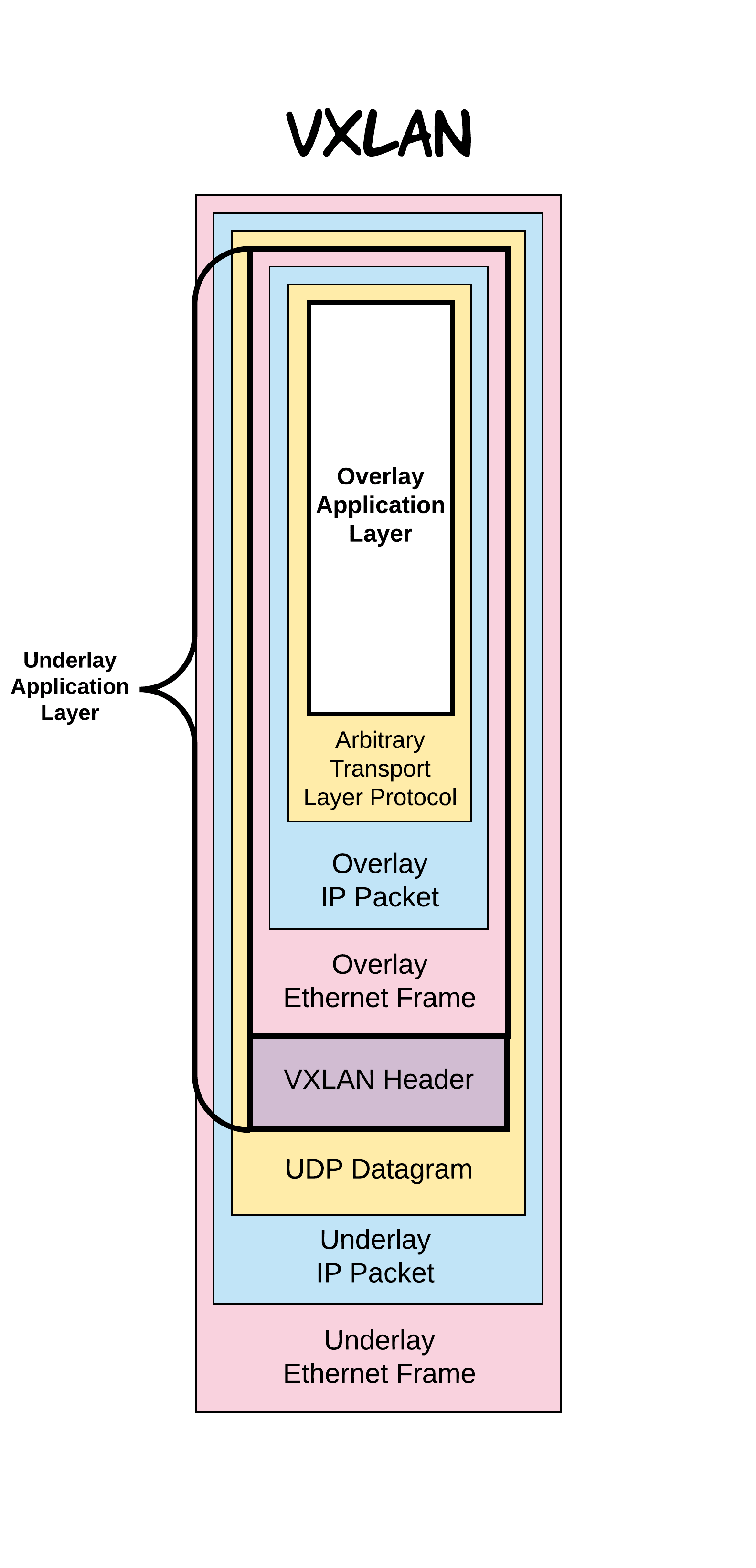
At its most basic level, VXLAN is a tunnelling protocol. In the case of VXLAN specifically, the tunnelled protocol is Ethernet. In other words, it’s merely another Ethernet frame put into a UDP packet, with a few extra bytes serving as a header — or a transport mechanism that supports the software controlling the devices that use the VXLAN.

Virtual Extensible LAN (VXLAN) is an encapsulation protocol for running an overlay network on existing Layer 3 infrastructure.

An overlay network is a virtual network that is built on top of existing network Layer 2 and Layer 3 technologies to support elastic compute architectures.

VXLAN makes it easier for network engineers to scale out a cloud computing environment while logically isolating cloud apps and tenants.

 From the packet switching point-of-view, VXLAN is just a matter of sticking some encapsulation on top of an L2 frame: something that other protocols do as well. The real difference it makes is at the control and management layer.


Need to mention is its available hardware support. While VxLAN can run well in software, some platforms implement VxLAN in hardware.

However, it does require multicast-enabled IP network and adjustment of MTU size on physical devices.

Ideally, one logical Layer 2 network is associated with one multicast group address. Sixteen million logical Layer 2 networks can be identified in VXLAN, using 24 bit field in the encapsulation header, but the multicast group addresses are limited (224.0.0.0 to 239.255.255.255). In some scenarios it might not be possible to have one to one mapping of a logical Layer 2 network to multicast group address. In such scenarios the vCloud Networking and Security Manager maps multiple logical networks to a multicast group address

 Also, the lack of control-plane in some setups means MAC address learning is done dynamically which could cause scalability problems. 


Benefits of VXLAN over pure L2

1.

Probably the greatest advantage a VXLAN solution has over a pure Layer 2 (L2) network is the elimination of the risks associated with L2 domains spanning multiple logical switches. For instance, an entirely L3 network with a VXLAN overlay is not susceptible to the spanning tree faults that have been experienced by some major Australian organizations.
Using STP to provide L2 loop free topology disables most redundant links. Hence, Equal-Cost Multi-Path (ECMP) is hard to achieve. However, ECMP is easy to achieve in IP network.

2.
Additionally, VXLAN is more scalable than pure L2, especially when control-plane learning is implemented, because excessive BUM (broadcast, unknown uni-cast and multicast) frame flooding is suppressed. This, combined with the fact that hardware VTEPs (explained below) minimize the latency overhead of VXLAN implementations, means we can build a network that is more scalable and robust, without sacrificing performance.

3.
Due to Server virtualization, each Virtual Machine (VM) requires a unique MAC address and an IP address. So, there are thousands of MAC table entries on upstream switches. This places much larger demand on table capacity of the switches. 

4.
VLANs are too restrictive in terms of distance and deployment. VTP can be used to deploy VLANs across the L2 switches but most people prefer to disable VTP due to its destructive nature.
5.
One historical concern with VLANs is the limited address space. Each device can have around 4000 usable VLANs. This is an issue with service providers. They may have to maintain several VLANs per customer, which exhausts the address space quickly. To work around this VLAN ID’s can be reused on different switches, or technologies like Q-in-Q can be used.

VxLAN does not have this limitation. It uses a 24-bit header, which 
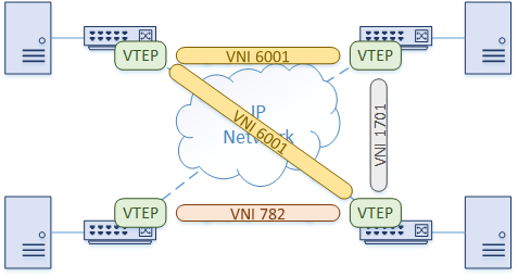
gives us about 16 million VNI’s to use. A VNI is the identifier for the LAN segment, similar to a VLAN ID. With an address space this large, an ID can be assigned to a customer, and it can remain unique across the entire network.

Overlay or underlay?

Overlay and underlay are terms frequently used in SDN and network virtualization. In terms of VXLAN, the underlay is the Layer 3 (L3) IP network that routes VXLAN packets as normal IP traffic. The overlay refers to the virtual Ethernet segment created by this forwarding.

Today is the time of cloud computing and extensive usage of data centers, where VXLAN is playing an important role for some companies, not to forget it has competitors too:)


For example, a L3 VXLAN switch (e.g. Cumulus), upon receiving a frame, may do any of the following:
· switch it locally if it is destined for a locally learnt MAC address (traditional Ethernet switching)
· forward it through a local VTEP, hence pushing it into the underlay encapsulated in VXLAN (in the overlay)
· route it at L3, pushing it into the underlay unencapsulated, which is just another IP packet.


Interaction between Overlays and Underlays


Introducing VTEP

The term VTEP (VXLAN Tunnel Endpoint) generally refers to any device that originates or terminates VXLAN traffic.
The encapsulation and decapsulation are handled by a component called a VTEP (VxLAN Tunnel End Point).  In the Cisco Nexus platform, this is also called an NVE interface.
There are two major types, based on how the encapsulation or de-encapsulation of VXLAN packets is handled: hardware VTEP devices handle VXLAN packets in hardware, while software VTEP devices handle VXLAN packets in software.

Examples of hardware VTEPs include switches and routers such as Cumulus switches, as we use in NTT’s environment. Software VTEPs include servers and hypervisors such as NSX-enabled ESXi hosts.

More specifically, a VTEP can refer to a virtual interface similar to an SVI that exists on such a device. Such an interface will often connect to the local device’s internal bridge implementation and act as the local source of VXLAN frames and the destination for remote MACs.


 As we have seen, VxLAN traffic is encapsulated before it is sent over the network. This creates stateless tunnels across the network, from the source switch to the destination switch.

Image result for VXLAN


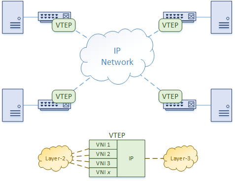
As shown in the diagram below, a VTEP has an IP address in the underlay network. It also has one or more VNI’s associated with it. When frames from one of these VNI’s arrives at the Ingress VTEP, the VTEP encapsulates it with UDP and IP headers.


The encapsulated packet is sent over the IP network to the Egress VTEP. When it arrives, the VTEP removes the IP and UDP headers, and delivers the frame as normal.


Packet Walk

Let’s take a moment to see how traffic passes through a simple VxLAN network.


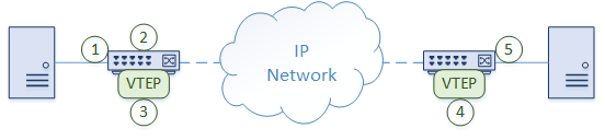
  1. A frame arrives on a switch port from a host. This port is a regular untagged (access) port, which assigns a VLAN to the traffic 
  2. The switch determines that the frame needs to be forwarded to another location. The remote switch is connected by an IP network. It may be close or many hops away
  3. The VLAN is associated with a VNI, so a VxLAN header is applied. The VTEP encapsulates the traffic in UDP and IP headers. UDP port 4789 is used as the destination port. The traffic is sent over the IP network
  4. The remote switch receives the packet and decapsulates it. A regular layer-2 frame with a VLAN ID is left
  5. The switch selects an egress port to send the frame out. This is based on normal MAC lookups. The rest of the process is as normal

Tips to remember:


1. 
It is important that the underlay is configured and working before the overlay is configured. Problems in the underlay will lead to problems in the overlay.

 2.

 The L2VNI is the bridge domain. This is for bridging hosts on the same layer-2 segment.

An L3VNI can be used to route between L2VNI’s. The ingress or egress VTEP can perform routing. This is called Symmetric IRB. Another form of routing called Asymmetric IRB, uses the ingress VTEP for routing and bridging, while the egress VTEP can only do bridging. Not a lot of vendors support asymmetric IRB.
A VTEP needs to know about all locally used L2VNI’s. It does not need to know about any L2VNI’s that it doesn’t need to support. A VTEP also needs to know about all L3VNI’s in use across the network.


3.


Multitenancy

Each L3VNI can be associated with a VRF. This makes multitenancy possible, in a similar way to MPLS.
Each VRF is still configured with a Route Distinguisher to keep it unique. Reachability information is imported and exported with Route Targets. Remember that you will need extended communities for this.
Each tenant can have one L3VNI, and many L2VNI’s.

 4.

 VxLAN is vendor-independent, so there are different ways it can be deployed. The two primary ways are Host Based and Gateway.

Hosts, such as a hypervisor, can have VxLAN configured on their virtual switches. Other devices, like firewalls and load-balancers, may also speak VxLAN natively.
In cases like this, there is no need to translate VLANs to VNI’s. Furthermore, the VTEPs are on the hosts themselves. The physical network infrastructure sees IP traffic, not VxLAN.


If the hosts do not support running VxLAN natively, or they just don’t use it, the switches can act as a VxLAN Gateway. Hosts belong to a VLAN. The switches map the VLAN to a VNI, and provide the VTEP functions.
In this model, the hosts are unaware of VxLAN, as the switches do all the work.
One advantage of this method is that VxLAN may (depending on platform) be implemented in hardware, providing performance benefits.


Of course, a combination of these two methods can be used. The switches can provide gateway services to some hosts, while other hosts speak VxLAN natively.

5.
VXLAN encapsulation adds between 50 and 54 bytes of additional header
information to the original Ethernet frame.

Because this can result in Ethernet frames  that exceed the default 1514 byte MTU, best practice is to implement jumbo frames  throughout the network,VxLAN adds quite a bit of overhead, so we need to increase the MTU size.
If we don’t do this, we may end up with fragmented packets, which can decrease performance.


6.

When multiple overlays co-exist on top of a common underlay network, resources like bandwidth should be provisioned to ensure that traffic form overlays can be accommodated and QoS objectives can be met. 

Overlays can have partially overlapping paths (nodes and links). Each overlay is selfish by nature.it sends traffic so as to optimize its own performance without considering the impact on other overlays, unless the underlay paths are traffic engineered on a per-overlay basis to avoid congestion of underlay resources.
Better visibility between overlays and underlays, or general coordination in placing overlay demands  on an underlay network, may be achieved by providing mechanisms to exchange performance and  liveliness information between the underlay and overlay(s) or by the use of such information by a coordination system.
Such information may include:
- Performance metrics (throughput, delay, loss, jitter)
- Cost metrics


7.

A VXLAN interface can have multiple VNIs, just like a trunk interface can have multiple VLANs. For example:
interface Vxlan 1
  vxlan source-interface loopback 1
  vxlan vlan 100 vni 10100
  vxlan vlan 200 vni 10200
  vxlan vlan 100 flood vtep 2.2.2.2 4.4.4.4
  vxlan vlan 200 flood vtep 2.2.2.2 3.3.3.3 4.4.4.4


Mindbox