Wednesday, January 5, 2011

Schmitt Trigger

References:
http://www.play-hookey.com/digital/experiments/rtl_schmitt.html


Sometimes an input signal to a digital circuit doesn't directly fit the description of a digital signal. For various reasons it may have slow rise and/or fall times, or may have acquired some noise that could be sensed by further circuitry. It may even be an analog signal whose frequency we want to measure. All of these conditions, and many others, require a specialized circuit that will "clean up" a signal and force it to true digital shape.

The required circuit is called a Schmitt Trigger. It has two possible states just like other multivibrators. However, the trigger for this circuit to change states is the input voltage level, rather than a digital pulse. That is, the output state depends on the input level, and will change only as the input crosses a pre-defined threshold.


The Schmitt Trigger makes its feedback connection through the emitters of the transistors as shown in the schematic diagram. To understand how this circuit works, assume that the input starts at ground, or 0 volts. Transistor Q1 is necessarily turned off, and has no effect on this circuit.

Therefore, RC1, R1, and R2 form a voltage divider across the 5 volt power supply to set the base voltage of Q2 to a value of (5 × R2)/(RC1 + R1 + R2). If we assume that the two transistors are essentially identical, then as long as the input voltage remains significantly less than the base voltage of Q2, Q1 will remain off and the circuit operation will not change.


While Q1 is off, Q2 is on. Its emitter and collector current are essentially the same, and are set by the value of RE and the emitter voltage, which will be less than the Q2 base voltage by VBE. If Q2 is in saturation under these circumstances, the output voltage will be within a fraction of the threshold voltage set by RC1, R1, and R2. It is important to note that the output voltage of this circuit cannot drop to zero volts, and generally not to a valid logic 0. We can deal with that, but we must recognize this fact.

Now, suppose that the input voltage rises, and continues to rise until it approaches the threshold voltage on Q2's base. At this point, Q1 begins to conduct. Since it now carries some collector current, the current through RC1 increases and the voltage at the collector of Q1 decreases. But this also affects our voltage divider, reducing the base voltage on Q2. But since Q1 is now conducting it carries some of the current flowing through RE, and the voltage across RE doesn't change as rapidly. Therefore, Q2 turns off and the output voltage rises to +5 volts. The circuit has just changed states.

If the input voltage rises further, it will simply keep Q1 turned on and Q2 turned off. However, if the input voltage starts to fall back towards zero, there must clearly be a point at which this circuit will reset itself. The question is, What is the falling threshold voltage? It will be the voltage at which Q1's base becomes more negative than Q2's base, so that Q2 will begin conducting again. However, it isn't the same as the rising threshold voltage, since Q1 is currently affecting the behavior of the voltage divider.

As VIN approaches this value, Q2 begins to conduct, taking emitter current away from Q1. This reduces the current through RC1 which raises Q2's base voltage further, increasing Q2's forward bias and decreasing Q1's forward bias. This in turn will turn off Q1, and the circuit will switch back to its original state.
Output level shifter for Schmitt Trigger
Three factors must be recognized in the Schmitt Trigger. First, the circuit will change states as VINapproaches VB2, not when the two voltages are equal. Therefore VB2 is very close to the threshold voltage, but is not precisely equal to it. For example, for the component values shown above, VB2 will be 2.54 volts when Q1 is held off, and 2.06 volts as VIN is falling towards this value.
Second, since the common emitter connection is part of the feedback system in this circuit, RE must be large enough to provide the requisite amount of feedback, without becoming so large as to starve the circuit of needed current. If RE is out of range, the circuit will not operate properly, and may not operate as anything more than a high-gain amplifier over a narrow input voltage range, instead of switching states.

The third factor is the fact that the output voltage cannot switch over logic levels, because the transistor emitters are not grounded. If a logic-level output is required, which is usually the case, we can use a circuit such as the one shown here to correct this problem. This circuit is basically two RTL inverters, except that one uses a PNP transistor. This works because when Q2 above is turned off, it will hold a PNP inverter off, but when it is on, its output will turn the PNP transistor on. The NPN transistor here is a second inverter to re-invert the signal and to restore it to active pull-down in common with all of our other logic circuits.

Quiz Time:

Answer 3 questions on the link:
http://www.wisc-online.com/objects/ViewObject.aspx?ID=SSE8507
Tuesday, January 4, 2011

Fundamental Loop Matrix

Sources:

http://www.transtutors.com/homework-help/Networks+%26+Systems/Network+Graph+Theories/loop-matrix-question.aspx

http://books.google.com/books?id=9c38IdqCbusC&pg=PA1119&lpg=PA1119&dq=define+fundamental+loop+matrix&source=bl&ots=63Jwqa6QEH&sig=Rqp4AG4sbnI5_eeyaVdgp_DK6AE&hl=en&ei=lfoiTaGdNo3KrAft56D-Cw&sa=X&oi=book_result&ct=result&resnum=5&ved=0CCEQ6AEwBA#v=onepage&q=define%20fundamental%20loop%20matrix&f=false

http://www.transtutors.com/homework-help/Networks+%26+Systems/Network+Graph+Theories/loop-matrix-question.aspx

Definition:


Consider a connected graph G with b branches and nt nodes. Select any arbitrary tree. The tree will contain n = nt - 1 tree branches (twigs) and l = (b - n) link branches. Every link defines a fundamental loop of the network. Let us take the example of the graph shown in Fig. a.
KVL For Fundamental Loops.PNG                    
                                              Fig.
Let T be a tree of G as shown in Fig. b. The number of fundamental loops of this graph will be (b - n) = 3. the three f-loop l1, l2 and l3 are shown in Fig. c. In order to apply KVL to each fundamental loop, we take reference direction of the loop which coincides with the reference direction of the link defining the loop.
   l1 : v1 + v2 + v5 + = 0 
   l2 : v2 + v3 + v4 = 0 
   l3 : v1 + v3 + v6 = 0
In matrix form, we can write
loop branch.PNG


Bf vb = 0   (KVL)    
Where  is an  matrix called the fundamental loop matrix or tie-set matrix
    Bf = [bkj]
Where bkj are the elements of bf the (k,j) element of the matrix is defined as follows:
   bkj = 1 when branch bj is in the f-loop lk and their reference directions (orientations) coincide
   bkj = -1 when branch bj is in the f-loop lk and has opposite orientation
   bkj = 0 when branch is not in the f-loop


Example:


In the graph shown in Fig. a tree consisting of branches 4, 5, 6, 7, 8 is chosen, as shown by heavy lines. Write the fundamental loop matrix of the graph.
SOLUTION
The fundamental loops defined by links {1, 2, 3} and their orientations are shown in Figs, c and d. Consider loop l1. It contains branches {1, 6, 8, 5}. The orientation of loop l1 is given the same orientation as its defining link 1. Therefore the element b11 is written 1. The directions of branches 6, 8 and 5 in l1 are the same as l1. therefore the entries
    fundamental loop matrix.PNG      
                      
FIG. 

b16,b18  and b15  are each equal to 1. Since branches 2, 3, 4 and 7 are not in loop b13 = 0,b14 = 0,b17 = 0.
Loop l2 contains branches {2, 6, 7}. The orientation of l2 is given the same orientation as its defining link. 2. Therefore the element b22 = 1. The orientations of branches 6 and 7 are opposite to the orientation of l2 consequently, b126 = -1 and b27 = -1 Since branches {1, 3, 4, 5, 8} are not contained in l2, b21 = 0,b23 = 0,b24 = 0,b25 = 0,b28  = 0.
Loop lhas branches (3, 4, 8, 7). The orientation of l3 is the same as that of its defining link 3.Therefore the element b33 = 1 The directions of branches 4 and 7 coincide with the orientation of l3 Hence b34 = 1, b37 = 1. The orientation of branch 8 does not coincide with the orientation of l3. Hence b38 = -1. Since branches {1, 2, 5, 6} are not contained in l3,b31 = 0, b32 = 0, b35 = 0, b36 = 0. Thus, we obtain the following matrix:

fundamental loop matrix a.PNG

Network Graphs

Reference:
http://venus.ece.ndsu.nodak.edu/ece/academics/courses/ee206/notes/cirtop.htm


Graph: a representation of a circuit where each branch is denoted by a line segment.


Tree (of a graph): a set of branches (each denoted by a line segment) that connects every node to every other node via some path without forming a loop.


Tree branch: a branch of a graph that is part of a particular tree.


Cotree: those branches of a graph which are not part of a particular tree. This is also known as the complement of the tree.

Link: a branch of a cotree.

Cut set: a minimum set of branches that, when cut, will divide a graph into two separate parts.

Fundamental cut set: a cut set containing only a single tree branch.

Fundamental loop: A loop that results when a link is put into the tree.

cut set divides a graph into two independent parts. In terms of the original circuit, a KCL equation can be written for either part of the circuit divided by the cut; such a KCL equation is called a cut-set equation.

The dual of a fundamental cut set is a fundamental loop. Each time a link is inserted into a tree as a potential tree branch, a loop is formed in the tree (thus the resulting object is no longer a tree). Such a loop is called a fundamental loop.

 Tree-branch analysis uses KCL (Kirchhoff's Current Law) but no reference node is selected like is done in nodal analysis; all KCL equations are written in terms of tree branch voltages instead of node voltages.

Loop analysis uses KVL (Kirchhoff's Voltage Law) but the loops chosen may not necessarily be meshes. Instead, each loop needs to be a fundamental loopobtained by inserting a link into a tree.


There is only one graph for a circuit (although there may be many ways to draw it). 

Usually, there are several trees for a graph, and each tree has a corresponding cotree

Monday, January 3, 2011

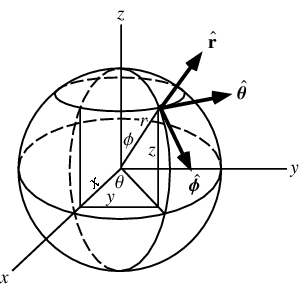
Spherical Co-ordinate System

http://mathworld.wolfram.com/SphericalCoordinates.html


SphericalCoordinates

1. Curvilinear co-ordinates

2. Used for describing positions on a sphere or spheroid

3. Denoted as set (r,  theta  (azimuthal angle), phi (polar angle) ) 


4.  Zenith
In spherical coordinates, the polar angle is the angle measured from the z-axis, denoted phi in this work, and also variously known as the zenith angle and colatitude. ,

 phi=90 degrees-delta ( where delta is the latitude) from the positive z-axis with 0<=phi<=pi

5. It is a logical extension of the usual polar coordinates notation, with theta remaining the angle in the xy-plane and phi becoming the angle out of that plane.

6. The symbol rho is sometimes also used in place of r, and phi and psi instead of phi. 

7. The spherical coordinates (r,theta,phi) are related to the Cartesian coordinates (x,y,z) by
r=sqrt(x^2+y^2+z^2)
(1)
theta=tan^(-1)(y/x)
(2)
phi=cos^(-1)(z/r),
where r in [0,infty)theta in [0,2pi), and phi in [0,pi], and the inverse tangent must be suitably defined to take the correct quadrant of (x,y) into account.

8. In terms of Cartesian coordinates,
x=rcosthetasinphi
(4)
y=rsinthetasinphi
(5)
z=rcosphi.

9. The line element is
 ds=drr^^+rdphiphi^^+rsinphidthetatheta^^,
(13)
the area element
 da=r^2sinphidthetadphir^^,
(14)
and the volume element
 dV=r^2sinphidphidthetadr.

http://en.wikipedia.org/wiki/Spherical_coordinate_system

10.  In geography and astronomy, the elevation and azimuth (or quantities very close to them) are called the latitude and longitude, respectively; and the radial distance is usually replaced by an altitude (measured from a central point or from a sea level surface).
11. Spherical coordinates are useful in analyzing systems that have some degree of symmetry about a point, such as volume integrals inside a sphere, the potential energy field surrounding a concentrated mass or charge, or global weather simulation in a planet's atmosphere. A sphere that has the Cartesian equation x2 + y2 + z2 = c2 has the simple equation r = c in spherical coordinates.
12.


Mindbox