Wednesday, October 12, 2011

PSLV-C18

Reference: http://isro.gov.in/index.aspx

Polar Satellite Launch Vehicle launched Megha-Tropiques satellite along with three auxiliary payloads- Jugnu and SRMSat (from India) and VesselSat-1 (from Luxembourg).Videos also available at the website.


Friday, October 7, 2011

Electronics Quiz

QuizMoz

POOJA GUPTA's Electronics quiz Score Report

Total number of questions:     11

Total number of correct answers:     9

Your QuizMoz Score:     82%

Average Score for this quiz:     54.5%

Number of people taken this quiz:     184

Maximum score for this quiz:     100%

More quizzes

Monday, September 5, 2011

Wireless Terms

Find wireless industry
terms, acronyms, and definitions instantly:
This industry dictionary is powered by Althos Wireless Dictionary

Tuesday, August 9, 2011

Integrating ADC

References:

1. http://en.wikipedia.org/wiki/Integrating_ADC
2.courses.engr.illinois.edu/ece581/int.ppt
3. http://www.maxim-ic.com/app-notes/index.mvp/id/1041
4. http://www.allaboutcircuits.com/vol_4/chpt_13/8.html


1.  Longer integration times allow for higher resolutions.


2.  Their use is typically limited to digital voltmeters and other instruments requiring highly accurate measurements.


3. One of the slowest ADCs.


4. Block diagram of dual-slope ADC:


5. Integrating analog-to-digital converters (ADCs) provide high resolution analog-to-digital conversions, with good noise rejection. 


6. It is possible to avoid using a DAC inside an ADC circuit if we substitute an analog ramping circuit and a digital counter with precise timing. in integrating single slope ADC, instead of using a DAC with a ramped output, we use an op-amp circuit called an integrator to generate a sawtooth waveform which is then compared against the analog input by a comparator. 

  The time it takes for the sawtooth waveform to exceed the input signal voltage level is measured by means of   a digital counter clocked with a precise-frequency square wave (usually from a crystal oscillator). 


7. Single-Slope ADC Architecture
The simplest form of an integrating ADC uses a single-slope architecture . Here, an unknown input voltage is integrated and the value compared against a known reference value. The time it takes for the integrator to trip the comparator is proportional to the unknown voltage (TINT/VIN). In this case, the known reference voltage must be stable and accurate to guarantee the accuracy of the measurement.


One drawback to this approach is that the accuracy is also dependent on the tolerances of the integrator's R and C values. Thus in a production environment, slight differences in each component's value change the conversion result and make measurement repeatability quite difficult to attain. To overcome this sensitivity to the component values, the dual-slope integrating architecture is used.


8. 

Dual-Slope ADC Architecture

A dual-slope ADC (DS-ADC) integrates an unknown input voltage (VIN) for a fixed amount of time (TINT), then "de-integrates" (TDEINT) using a known reference voltage (VREF) for a variable amount of time (see Figure 2).

Figure 2. Dual-slope integration.

The key advantage of this architecture over the single-slope is that the final conversion result is insensitive to errors in the component values. That is, any error introduced by a component value during the integrate cycle will be cancelled out during the de-integrate phase. In equation form:

Vin × TINT = VREF × TDEINT

or

TDEINT = TINT × (VIN / VREF)

From this equation, we see that the de-integrate time is proportional to the ratio of VIN / VREF. A complete block diagram of a dual-slope converter is shown in Figure 3.

Figure 3. Dual-slope converter.


9. In the dual-slope converter, an integrator circuit is driven positive and negative in alternating cycles to ramp down and then up, rather than being reset to 0 volts at the end of every cycle. In one direction of ramping, the integrator is driven by the positive analog input signal (producing a negative, variable rate of output voltage change, or output slope) for a fixed amount of time, as measured by a counter with a precision frequency clock. 

Then, in the other direction, with a fixed reference voltage (producing a fixed rate of output voltage change) with time measured by the same counter. The counter stops counting when the integrator's output reaches the same voltage as it was when it started the fixed-time portion of the cycle. The amount of time it takes for the integrator's capacitor to discharge back to its original output voltage, as measured by the magnitude accrued by the counter, becomes the digital output of the ADC circuit.

Question IES 2011:

With a block diagram, explain the function of a dual slope DVM.

A dual slope integrating type of A/D converter has an integrating capacitor of 0.1 uF and a resistance of 100 k ohm. the reference voltage is 2 V and the output of the integrator is not to exceed 10 V. What is the maximum time required for the output voltage to be integrated?

Answer:
check this link:


DVM is essentially an Analog to digital converter (A/D) with a digital display.
It uses dual slope integrating type A/D converter as explained above.

Maximum time taken by integrator = R * C = .01 sec = 10 ms

relative value corresponding to 10 V = 5 * 10 ms = 50 ms.

Anybody having a different viewpoint for this problem, kindly share the same.

Sunday, June 26, 2011

RS-485

Reference Links:
http://www.lammertbies.nl/comm/info/RS-485.html
http://www.interworldna.com/accesio/serial/usb-232-422485.html
http://digital.ni.com/public.nsf/allkb/B9A38929D546B796862572C7005F0644
http://www.arcelect.com/485info.htm

RS-232 is the single ended serial protocol and RS-485 and RS-422 are differential serial protocol. The pinout for RS-232, RS-422 and RS-485 is shown below figure.
A loopback test is a test in which a signal in sent from a communications device and returned (looped back) to it as a way to determine whether the device is working right. The figures below will show you what pins you need to connect to perform loopback test on RS-232 and RS-422/RS-485 respectively.
RS-232

RS-422 and RS-485


RS485 will support 32 drivers and 32 receivers (we are talking about bi-directional - half duplex - multi-drop communications over a single or dual twisted pair cable !!).  An RS-485 network can be connected in a 2 or 4 wire mode.  Maximum cable length can be as much as 4000 feet because of the differential voltage transmission system used. The typical use for RS485 is a single PC connected to several addressable devices that share the same cable. You can think of RS485 as a "party-lined" communications system (the addressing is handled by the Remote Computer unit). The RS232 may be converted to RS485 with a simple interface converter - it can have optical isolation and surge suppression.


RS232 is an interface to connect one DTE, data terminal equipment to one DCE, data communication equipment at a maximum speed of 20 kbps with a maximum cable length of 50 feet. This was sufficient in the old days where almost all computer equipment were connected using modems, but soon after people started to look for interfaces capable of one or more of the following:
  • Connect DTE's directly without the need of modems
  • Connect several DTE's in a network structure
  • Ability to communicate over longer distances
  • Ability to communicate at faster communication rates
RS485 is the most versatile communication standard in the standard series defined by the EIA, as it performs well on all four points. That is why RS485 is currently a widely used communication interface in data acquisition and control applications where multiple nodes communicate with each other.


RS485 functionality

Default, all the senders on the RS485 bus are in tri-state with high impedance. In most higher level protocols, one of the nodes is defined as a master which sends queries or commands over the RS485 bus. All other nodes receive these data. Depending of the information in the sent data, zero or more nodes on the line respond to the master. In this situation, bandwidth can be used for almost 100%. There are other implementations of RS485 networks where every node can start a data session on its own. This is comparable with the way ethernet networks function. Because there is a chance of data collosion with this implementation, theory tells us that in this case only 37% of the bandwidth will be effectively used. With such an implementation of a RS485 network it is necessary that there is error detection implemented in the higher level protocol to detect the data corruption and resend the information at a later time.
There is no need for the senders to explicity turn the RS485 driver on or off. RS485 drivers automatically return to their high impedance tri-state within a few microseconds after the data has been sent. Therefore it is not needed to have delays between the data packets on the RS485 bus.

Wednesday, June 22, 2011

Trace your Internet message

Reference: http://communication.howstuffworks.com/convergence/router10.htm


Tracing a Message

If you're using a Microsoft Windows-based system, you can see just how many routers are involved in your Internet traffic by using a program you have on your computer. The program is called Traceroute, and that describes what it does -- it traces the route that a packet of information takes to get from your computer to another computer connected to the Internet. To run this program, click on the "MS-DOS Prompt" icon on the "Start" menu. Then, at the"C:\WINDOWS>" prompt, type "tracert www.howstuffworks.com". When I did this from my office in Florida, the results looked like this:

The first number shows how many routers are between your computer and the router shown. In this instance, there were a total of 14 routers involved in the process (number 15 is the Howstuffworks.com Web server). The next three numbers show how long it takes a packet of information to move from your computer to the router shown and back again. Next, in this example, starting with step six, comes the "name" of the router or server. This is something that helps people looking at the list but is of no importance to the routers and computers as they move traffic along the Internet. Finally, you see the Internet Protocol (IP) address of each computer or router. The final picture of this trace route shows that there were 14 routers between the Web server and me and that it took, on average, a little more than 2.5 seconds for information to get from my computer to the server and back again.
You can use Traceroute to see how many routers are between you and any other computer you can name or know the IP address for. It can be interesting to see how many steps are required to get to computers outside your nation. Since I live in the United States, I decided to see how many routers were between my computer and the Web server for the British Broadcasting Corporation. At the C:\WINDOWS> prompt, I typed tracert www.bbc.com. The result was this:

You can see that it took only one more step to reach a Web server on the other side of the Atlantic Ocean than it did to reach a server two states away!

It surely works, when tried from a place in North India;

C:\>cd windows

C:\WINDOWS>tracert www.howstuffworks.com

Tracing route to a462.g.akamai.net [96.17.182.8]
over a maximum of 30 hops:

  1    <1 ms    <1 ms    <1 ms  192.168.1.1
  2    30 ms    31 ms    33 ms  ABTS-North-Static-157.130.160.122.airtelbroadband.in [122.160.130.157]
  3    29 ms    31 ms    29 ms  ABTS-North-Static-153.130.160.122.airtelbroadband.in [122.160.130.153]
  4    30 ms    31 ms    29 ms  125.19.22.145
  5    30 ms    30 ms    31 ms  59.145.7.230
  6    30 ms    34 ms    34 ms  a96-17-182-8.deploy.akamaitechnologies.com [96.17.182.8]

Trace complete.

C:\WINDOWS>

C:\WINDOWS>tracert www.yahoo.com

Tracing route to any-fp.wa1.b.yahoo.com [69.147.125.65]
over a maximum of 30 hops:

  1    <1 ms    <1 ms    <1 ms  192.168.1.1
  2    35 ms    47 ms    31 ms  ABTS-North-Static-157.130.160.122.airtelbroadband.in [122.160.130.157]
  3    31 ms    29 ms    29 ms  ABTS-North-Static-149.130.160.122.airtelbroadband.in [122.160.130.149]
  4    29 ms    29 ms    29 ms  203.101.83.197
  5    50 ms    50 ms    49 ms  203.101.100.22
  6   195 ms   195 ms   195 ms  so-4-0-3-zcr2.lnt.cw.net [166.63.223.69]
  7   195 ms   195 ms   195 ms  so-5-2-0-dcr2.tsd.cw.net [195.2.10.134]
  8   205 ms   195 ms   195 ms  xe-0-3-0-xcr1.lnd.cw.net [195.2.25.1]
  9   306 ms   325 ms   306 ms  ge-11-0-0-xcr1.nyk.cw.net [195.2.25.18]
 10   359 ms   276 ms   277 ms  pat1.nyc.yahoo.com [198.32.118.24]
 11   279 ms   279 ms   279 ms  ae-8.pat1.dcp.yahoo.com [216.115.101.157]
 12   277 ms   294 ms   294 ms  ae-2-d170.msr2.re1.yahoo.com [216.115.108.69]
 13   305 ms   280 ms   278 ms  te-9-4.bas-a2.re1.yahoo.com [66.196.112.203]
 14   277 ms   276 ms   280 ms  ir1.fp.vip.re1.yahoo.com [69.147.125.65]

Trace complete.


Tuesday, June 21, 2011

How XM Radio Works


Reference: 
http://www.tech-faq.com/how-xm-radio-works.html


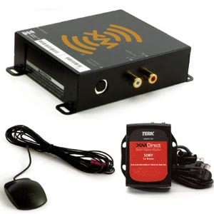
XM Radio is a satellite radio service. Satellite radio is a technology that for the most part has been around for many years. For instance, many television studios have been using satellites to beam TV signals from far away locations to viewers for decades, however satellite radio has been in operation in America since 2001.
Satellite radio is pretty easy to describe. The programs for satellite radio include music, talk shows, live sporting events and sport analysis shows. These shows are usually sent from one central location, where they are sent from the ground to satellites rotating in space that then broadcast the signal to those listeners with the hardware such as special antennas and receivers to pick up the signal. Here is some more information
XM Radio1 How XM Radio Works

Satellite Radio Starts from the Broadcaster

It is important to note that XM satellite radio initially starts from the studio, where the programming is put together. Programming such as music, talk shows, sports analysis shows, etc are created and then transmitted usually from a main source to two satellites over head. (It is also possible that live events such as news or sporting events are sent individually directly from the location where they are happening to the two satellites overhead). Usually programming is digitized and then compressed to fit lots of data into a small bandwidth of radio frequency which XM satellite is allowed to operate on.

The Satellites

XM Radio has two satellites that are in geostationary orbit located above the equator. Geostationary orbit means that the satellites are moving at the same speed as the earth turns, making it able to be in the same position as the earth at all times. This way, XM satellite radio can always be pointing to their satellites and feeding them programming and the satellites can easily broadcast their signal to the millions of listeners that have antennas and receivers pointed towards the geostationary satellite.

Antenna

A special antenna is necessary to receive XM satellite radio. Usually these antennas are very small in size, smaller than a normal tennis ball and can be placed on top of car roofs, in an office or at home. They are not that expensive and cost usually less than $50. These antennas make it possible to catch the specific digital radio signal that is broadcasted and send it to the special XM Satellite Receiver.

Satellite Repeaters

Because satellites that are in geostationary orbit, their antennas must have a clear line of sight to the southern sky to pick up signals clearly. Obviously not everyone will have a clear line of sight (especially if you live in an urban location) so a technique used to increase the likelihood of anyone using this technology to have good reception are repeaters. A repeater is a large antenna located in key positions around the country, where a satellite signal can be received and then repeated or rebroadcasted to antennas facing any direction, south, north, east, west and in between.

Satellite Receivers

Satellite receivers enable listeners to receive the digital audio broadcasts being relayed off of the satellites in geostationary orbit. These satellite receivers come in many different styles and some have different functions. They all include a chipset that can decode the encrypted signal sent from the satellite. The satellite sends its programming signal encrypted so that people that do not have a receiver or do not pay the monthly subscription fee can not have access to it.
Receivers can come in the form of auto car stereos, add on receivers that hook up to your already installed car stereo, boom boxes, home audio receivers with satellite receiver capability and portable devices that allow you to pick up the satellite signal no matter where you go. These portable devices have their own energy source and are similar to size and shape as iPod's. These receivers usually cost from about $30 to over $300.

Wednesday, January 5, 2011

Schmitt Trigger

References:
http://www.play-hookey.com/digital/experiments/rtl_schmitt.html


Sometimes an input signal to a digital circuit doesn't directly fit the description of a digital signal. For various reasons it may have slow rise and/or fall times, or may have acquired some noise that could be sensed by further circuitry. It may even be an analog signal whose frequency we want to measure. All of these conditions, and many others, require a specialized circuit that will "clean up" a signal and force it to true digital shape.

The required circuit is called a Schmitt Trigger. It has two possible states just like other multivibrators. However, the trigger for this circuit to change states is the input voltage level, rather than a digital pulse. That is, the output state depends on the input level, and will change only as the input crosses a pre-defined threshold.


The Schmitt Trigger makes its feedback connection through the emitters of the transistors as shown in the schematic diagram. To understand how this circuit works, assume that the input starts at ground, or 0 volts. Transistor Q1 is necessarily turned off, and has no effect on this circuit.

Therefore, RC1, R1, and R2 form a voltage divider across the 5 volt power supply to set the base voltage of Q2 to a value of (5 × R2)/(RC1 + R1 + R2). If we assume that the two transistors are essentially identical, then as long as the input voltage remains significantly less than the base voltage of Q2, Q1 will remain off and the circuit operation will not change.


While Q1 is off, Q2 is on. Its emitter and collector current are essentially the same, and are set by the value of RE and the emitter voltage, which will be less than the Q2 base voltage by VBE. If Q2 is in saturation under these circumstances, the output voltage will be within a fraction of the threshold voltage set by RC1, R1, and R2. It is important to note that the output voltage of this circuit cannot drop to zero volts, and generally not to a valid logic 0. We can deal with that, but we must recognize this fact.

Now, suppose that the input voltage rises, and continues to rise until it approaches the threshold voltage on Q2's base. At this point, Q1 begins to conduct. Since it now carries some collector current, the current through RC1 increases and the voltage at the collector of Q1 decreases. But this also affects our voltage divider, reducing the base voltage on Q2. But since Q1 is now conducting it carries some of the current flowing through RE, and the voltage across RE doesn't change as rapidly. Therefore, Q2 turns off and the output voltage rises to +5 volts. The circuit has just changed states.

If the input voltage rises further, it will simply keep Q1 turned on and Q2 turned off. However, if the input voltage starts to fall back towards zero, there must clearly be a point at which this circuit will reset itself. The question is, What is the falling threshold voltage? It will be the voltage at which Q1's base becomes more negative than Q2's base, so that Q2 will begin conducting again. However, it isn't the same as the rising threshold voltage, since Q1 is currently affecting the behavior of the voltage divider.

As VIN approaches this value, Q2 begins to conduct, taking emitter current away from Q1. This reduces the current through RC1 which raises Q2's base voltage further, increasing Q2's forward bias and decreasing Q1's forward bias. This in turn will turn off Q1, and the circuit will switch back to its original state.
Output level shifter for Schmitt Trigger
Three factors must be recognized in the Schmitt Trigger. First, the circuit will change states as VINapproaches VB2, not when the two voltages are equal. Therefore VB2 is very close to the threshold voltage, but is not precisely equal to it. For example, for the component values shown above, VB2 will be 2.54 volts when Q1 is held off, and 2.06 volts as VIN is falling towards this value.
Second, since the common emitter connection is part of the feedback system in this circuit, RE must be large enough to provide the requisite amount of feedback, without becoming so large as to starve the circuit of needed current. If RE is out of range, the circuit will not operate properly, and may not operate as anything more than a high-gain amplifier over a narrow input voltage range, instead of switching states.

The third factor is the fact that the output voltage cannot switch over logic levels, because the transistor emitters are not grounded. If a logic-level output is required, which is usually the case, we can use a circuit such as the one shown here to correct this problem. This circuit is basically two RTL inverters, except that one uses a PNP transistor. This works because when Q2 above is turned off, it will hold a PNP inverter off, but when it is on, its output will turn the PNP transistor on. The NPN transistor here is a second inverter to re-invert the signal and to restore it to active pull-down in common with all of our other logic circuits.

Quiz Time:

Answer 3 questions on the link:
http://www.wisc-online.com/objects/ViewObject.aspx?ID=SSE8507

Tuesday, January 4, 2011

Fundamental Loop Matrix

Sources:

http://www.transtutors.com/homework-help/Networks+%26+Systems/Network+Graph+Theories/loop-matrix-question.aspx

http://books.google.com/books?id=9c38IdqCbusC&pg=PA1119&lpg=PA1119&dq=define+fundamental+loop+matrix&source=bl&ots=63Jwqa6QEH&sig=Rqp4AG4sbnI5_eeyaVdgp_DK6AE&hl=en&ei=lfoiTaGdNo3KrAft56D-Cw&sa=X&oi=book_result&ct=result&resnum=5&ved=0CCEQ6AEwBA#v=onepage&q=define%20fundamental%20loop%20matrix&f=false

http://www.transtutors.com/homework-help/Networks+%26+Systems/Network+Graph+Theories/loop-matrix-question.aspx

Definition:


Consider a connected graph G with b branches and nt nodes. Select any arbitrary tree. The tree will contain n = nt - 1 tree branches (twigs) and l = (b - n) link branches. Every link defines a fundamental loop of the network. Let us take the example of the graph shown in Fig. a.
KVL For Fundamental Loops.PNG                    
                                              Fig.
Let T be a tree of G as shown in Fig. b. The number of fundamental loops of this graph will be (b - n) = 3. the three f-loop l1, l2 and l3 are shown in Fig. c. In order to apply KVL to each fundamental loop, we take reference direction of the loop which coincides with the reference direction of the link defining the loop.
   l1 : v1 + v2 + v5 + = 0 
   l2 : v2 + v3 + v4 = 0 
   l3 : v1 + v3 + v6 = 0
In matrix form, we can write
loop branch.PNG


Bf vb = 0   (KVL)    
Where  is an  matrix called the fundamental loop matrix or tie-set matrix
    Bf = [bkj]
Where bkj are the elements of bf the (k,j) element of the matrix is defined as follows:
   bkj = 1 when branch bj is in the f-loop lk and their reference directions (orientations) coincide
   bkj = -1 when branch bj is in the f-loop lk and has opposite orientation
   bkj = 0 when branch is not in the f-loop


Example:


In the graph shown in Fig. a tree consisting of branches 4, 5, 6, 7, 8 is chosen, as shown by heavy lines. Write the fundamental loop matrix of the graph.
SOLUTION
The fundamental loops defined by links {1, 2, 3} and their orientations are shown in Figs, c and d. Consider loop l1. It contains branches {1, 6, 8, 5}. The orientation of loop l1 is given the same orientation as its defining link 1. Therefore the element b11 is written 1. The directions of branches 6, 8 and 5 in l1 are the same as l1. therefore the entries
    fundamental loop matrix.PNG      
                      
FIG. 

b16,b18  and b15  are each equal to 1. Since branches 2, 3, 4 and 7 are not in loop b13 = 0,b14 = 0,b17 = 0.
Loop l2 contains branches {2, 6, 7}. The orientation of l2 is given the same orientation as its defining link. 2. Therefore the element b22 = 1. The orientations of branches 6 and 7 are opposite to the orientation of l2 consequently, b126 = -1 and b27 = -1 Since branches {1, 3, 4, 5, 8} are not contained in l2, b21 = 0,b23 = 0,b24 = 0,b25 = 0,b28  = 0.
Loop lhas branches (3, 4, 8, 7). The orientation of l3 is the same as that of its defining link 3.Therefore the element b33 = 1 The directions of branches 4 and 7 coincide with the orientation of l3 Hence b34 = 1, b37 = 1. The orientation of branch 8 does not coincide with the orientation of l3. Hence b38 = -1. Since branches {1, 2, 5, 6} are not contained in l3,b31 = 0, b32 = 0, b35 = 0, b36 = 0. Thus, we obtain the following matrix:

fundamental loop matrix a.PNG

Network Graphs

Reference:
http://venus.ece.ndsu.nodak.edu/ece/academics/courses/ee206/notes/cirtop.htm


Graph: a representation of a circuit where each branch is denoted by a line segment.


Tree (of a graph): a set of branches (each denoted by a line segment) that connects every node to every other node via some path without forming a loop.


Tree branch: a branch of a graph that is part of a particular tree.


Cotree: those branches of a graph which are not part of a particular tree. This is also known as the complement of the tree.

Link: a branch of a cotree.

Cut set: a minimum set of branches that, when cut, will divide a graph into two separate parts.

Fundamental cut set: a cut set containing only a single tree branch.

Fundamental loop: A loop that results when a link is put into the tree.

cut set divides a graph into two independent parts. In terms of the original circuit, a KCL equation can be written for either part of the circuit divided by the cut; such a KCL equation is called a cut-set equation.

The dual of a fundamental cut set is a fundamental loop. Each time a link is inserted into a tree as a potential tree branch, a loop is formed in the tree (thus the resulting object is no longer a tree). Such a loop is called a fundamental loop.

 Tree-branch analysis uses KCL (Kirchhoff's Current Law) but no reference node is selected like is done in nodal analysis; all KCL equations are written in terms of tree branch voltages instead of node voltages.

Loop analysis uses KVL (Kirchhoff's Voltage Law) but the loops chosen may not necessarily be meshes. Instead, each loop needs to be a fundamental loopobtained by inserting a link into a tree.


There is only one graph for a circuit (although there may be many ways to draw it). 

Usually, there are several trees for a graph, and each tree has a corresponding cotree

Mindbox